
一所懸命HW設計者のふりをやっとる現代のC++が大嫌いなSWの開発者。
FPGAのGPUと家庭用ゲーム機の設計、うちの猫(ニュートリノ+コスモス)、百人一首、競技かるた、お箏の演奏、ゲーム開発、抹茶+和菓子
投稿は私個人の意見で、会社を代表するものやない
Boring people will tell you the Hello World of FPGA dev is a blinking LED. But we are not boring people, we are developers of custom graphics hardware. And as developers of custom graphics hardware, we need a flashy test befitting of our status as the cool kidztm of the FPGA world. Something impressive we can show off to our non-technical friends, that gets us excited about what is possible. We need… an HDMI test pattern!
In this blog post, I will walk you through setting up your Vivado environment, and testing it by actually outputting something to the screen. You won’t need Vitis yet, but I am assuming you at least installed Vivado. But before jumping in, there are a few extra goodies you are going to need
First, Vivado may not have built-in support for your board in the default install, but it can be added via board support files. I use the Zybo Z7, and Digilent provides the board packages here, with instructions for adding them to Vivado here, although some of those screenshots look like they might be from a much older version of Vivado. After adding the board support files, it should be trivial to create a new project for your specific board
You will also need a constraint file. Constraint files do things like telling Vivado about the pins on your board, where they are, and what they are used for, as well as specifying some timing constraints, and additional info. Digilent keeps these xdc files here, so choose the one matching your board and save it somewhere
This last one is controversial. I have a custom TMDS encoder I made, but having to explain Transition Minimised Differential Signalling here would 0) make this post way too long, 1) introduce way too many new concepts (including CDCs) in one post, and 2) put way too much time and work between you and getting your first pattern on screen. Therefore for the initial test only, I recommend you download Digilent’s TMDS IP, called dvi2tmds. If all the previous steps are done, we’re now ready to jump into our first project!
Launch Vivado and select Create Project, choose RTL project with no sources specified, and continue on to the part select. Switching from the parts tab to the board tab, you should see your board in the list, assuming you installed the previously mentioned board files. Congratulations, you just made your very first project!
In the Sources pane, you will see Design Sources, Constraints, Simulation Sources, and Utility Sources. Click on the + button, select Add or create constraints → Add files, and navigate to where you saved the Master.xdc, after which the file should appear in your constraints
Double click on the file to open it and take a quick look. You’ll see lots of entries for useful looking things, but the first thing we need is to uncomment the clock pin
#Clock signal
set_property -dict { PACKAGE_PIN K17   IOSTANDARD LVCMOS33 } [get_ports { sysclk }]; #IO_L12P_T1_MRCC_35 Sch=sysclk
create_clock -add -name sys_clk_pin -period 8.00 -waveform {0 4} [get_ports { sysclk }];
This is how we tell Vivado about the clock pin, including it’s location (K17), IO standard (3.3v CMOS), and period (8ns or 125MHz). It also sets the name to sysclk, and using that name in our top level module port list will allow us to access the clock. To create the top level module, click the + button, go to Add or create design sources → Create file, select SystemVerilog from the File type dialog, and set the file name to top.sv or something similar. Click the finish button, skip adding ports, and after all that, top.sv will appear under Design Sources in the Sources pane. Double click the file to open it and add the following code
`timescale 1ns / 1ps
`default_nettype none

// sysclk is the name defined in my constraints file
module top(input wire logic sysclk);
	always_ff @(posedge sysclk) begin
		// your code here
	end
endmodule
That code does nothing, but it shows how using the name defined in the constraints file allows you to access the fun bits. Now let’s do the same thing for some of the HDMI TX pins in the constraint file, this time uncommenting hdmi_tx_clk_n, hdmi_tx_clk_p, hdmi_tx_n, and hdmi_tx_p. The other pins (hpd, scl, sda) can be skipped.
##HDMI TX
#set_property -dict { PACKAGE_PIN E18 IOSTANDARD LVCMOS33 } [get_ports { hdmi_tx_hpd }];
#set_property -dict { PACKAGE_PIN G17 IOSTANDARD LVCMOS33 } [get_ports { hdmi_tx_scl }];
#set_property -dict { PACKAGE_PIN G18 IOSTANDARD LVCMOS33 } [get_ports { hdmi_tx_sda }];
set_property -dict { PACKAGE_PIN H17 IOSTANDARD TMDS_33 } [get_ports { hdmi_tx_clk_n }];
set_property -dict { PACKAGE_PIN H16 IOSTANDARD TMDS_33 } [get_ports { hdmi_tx_clk_p }];
set_property -dict { PACKAGE_PIN D20 IOSTANDARD TMDS_33 } [get_ports { hdmi_tx_n[0] }];
set_property -dict { PACKAGE_PIN D19 IOSTANDARD TMDS_33 } [get_ports { hdmi_tx_p[0] }];
set_property -dict { PACKAGE_PIN B20 IOSTANDARD TMDS_33 } [get_ports { hdmi_tx_n[1] }];
set_property -dict { PACKAGE_PIN C20 IOSTANDARD TMDS_33 } [get_ports { hdmi_tx_p[1] }];
set_property -dict { PACKAGE_PIN A20 IOSTANDARD TMDS_33 } [get_ports { hdmi_tx_n[2] }];
set_property -dict { PACKAGE_PIN B19 IOSTANDARD TMDS_33 } [get_ports { hdmi_tx_p[2] }];
Our top level module then becomes
module top(
	input wire logic sysclk,		// system clock
	output wire logic hdmi_tx_clk_n,	// TMDS clock negative
	output wire logic hdmi_tx_clk_p,	// TMDS clock positive
	output wire logic [2:0] hdmi_tx_n,	// 3ch data, negative
	output wire logic [2:0] hdmi_tx_p);	// 3ch data, positive
At this point, we’ve gone as far as possible without actually knowing how HDMI works, so it’s time to introduce you to your new best friend: Project F’s excellent HDMI timing page. Our design will be locked to 640×480@60Hz, and this page is where we’ll get the parameters from. First, draw your attention to Green-san’s diagram of the various regions
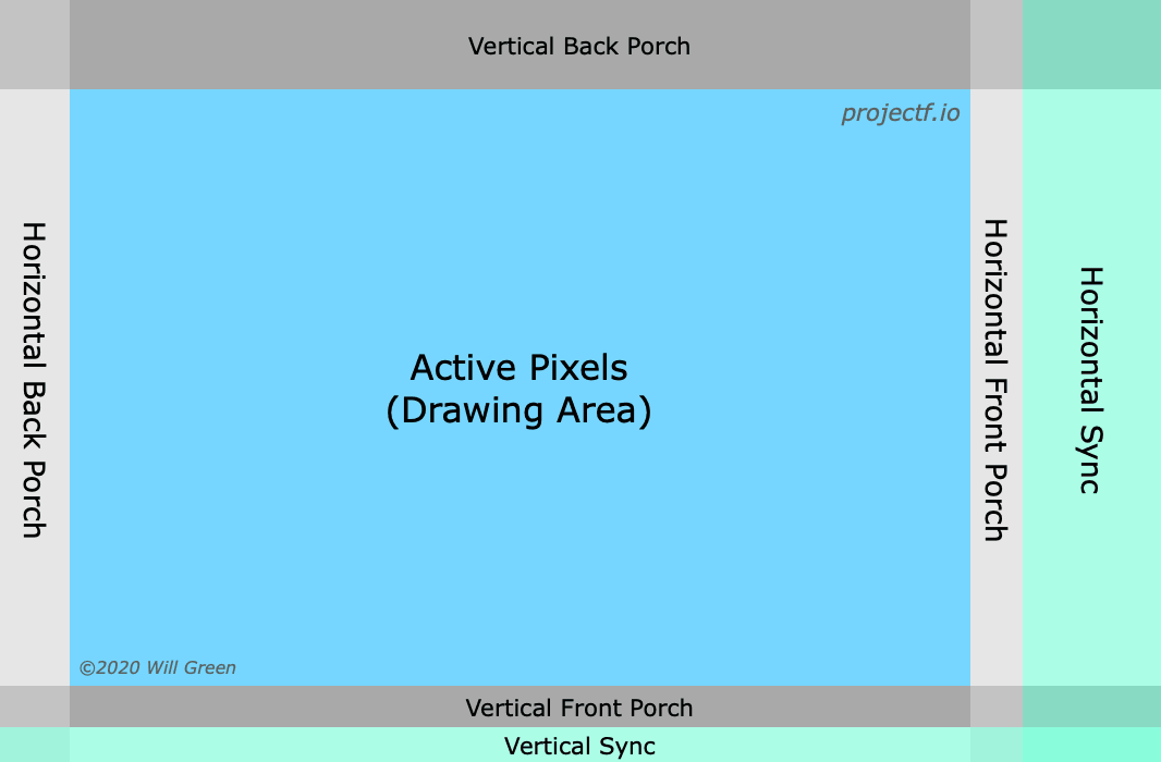
We’re going to want to output colours while we’re in the active pixel area, and generate signals to tell the monitor when we’re in the horizontal and vertical sync areas. For horizontal, the width of the active area is 640px, the front porch is 16px, horizontal sync is 96px, and back porch is 48px, giving a total width of 640 + 160 = 800 pixels. Vertical works similarly, with the active area being 480px, the front porch being 10px, the vsync being 2px, and the back porch being 33px, giving a total height of 480 + 45 = 525 pixels. 800 x 525 = 420,000 pixels, and given the 39.721946ns pixel clock period, that’s 16.683ms
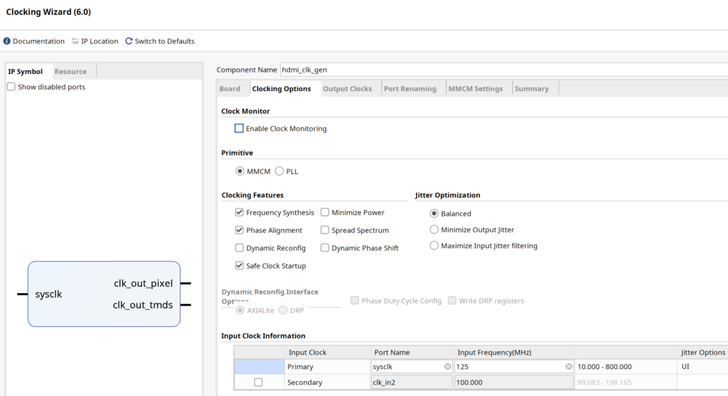
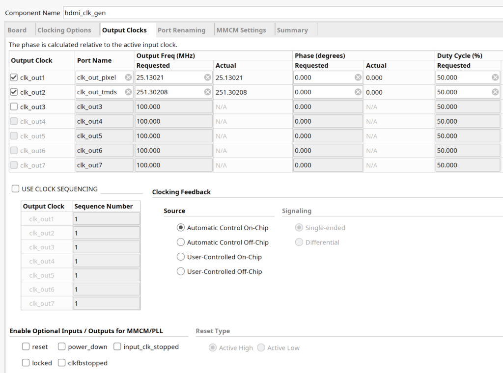
Let’s talk clocks! HDMI requires two clocks: a pixel clock set to 25.175MHz and a TMDS clock set to 251.75MHz. I usually use 25MHz and 250MHz, but that’s technically out of the tolerance band and not guaranteed to work with all monitors. You’ll notice the TMDS clock is exactly 10x the pixel clock, and this is because TMDS wants to shift out 10 bits for every pixel. Technically the Digilent TMDS IP can generate the TMDS clock from the pixel clock, but this only works for 720p or higher
To actually generate clocks, we have a few options. If you are using Zynq, there are four fabric clocks that can be enabled and configured to a reasonable range of frequencies. For everyone else, you can instantiate a MMCM or PLL directly, but its much easier to use the Clocking Wizard in the IP Catalog. Go to the Flow Navigator pane, click on PROJECT MANAGER → IP Catalog, and search for Clocking Wizard. Configure it as follows, swapping in the correct clock frequency for your sysclk. You remember, the one in your constraints file!
The clock wizard can then be used in RTL as follows
// generate the needed HDMI clocks
logic pixel_clk_25;
logic tmds_clk_250;
hdmi_clk_gen clk_gen(
	.sysclk(sysclk),		// input sysclk
	.clk_out_pixel(pixel_clk_25),	// output 25MHz pixel clock
	.clk_out_tmds(tmds_clk_250));	// output 250MHz TMDS clock

always_ff @(posedge pixel_clk_25) begin
	// your HDMI code here
end
Now we have to instantiate the Digilent TMDS IP you hopefully added in the initial setup steps. Go back to the IP Catalog, search for rgb2dvi, and click on it to customise. If you don’t see it in the IP Catalog, you may have forgotten to add vivado-library-master to the IP Repo list in settings.
Once you are customising rgb2dvi, give it the name rgb2dvi_0, and be sure to disable both Reset active high and Generate SerialClk internally from pixel clock, and click OK to generate the IP. Instantiate it with the following RTL
// signals to drive the sync stuff
logic [2:0][7:0] colour24 = 0;
logic hsync = 0;
logic vsync = 0;
logic draw_area = 0;
// instantiate the HDMI TMDS encoder
rgb2dvi_0 tmds_encoder(
// RGB in
.aRst(1'b0), // input: unused
.PixelClk(pixel_clk_25), // input: 25MHz pixel clock
.vid_pData(colour24), // input: 8b x 3ch colour data
.vid_pHSync(hsync), // input: are we in hsync?
.vid_pVSync(vsync), // input: are we in vsync?
.vid_pVDE(draw_area), // input: are we in the draw area?
// TMDS out
.SerialClk(tmds_clk_250), // input: 250MHz TMDS clock
.TMDS_Clk_p(hdmi_tx_clk_p), // output: positive HDMI clock
.TMDS_Clk_n(hdmi_tx_clk_n), // output: negative HDMI clock
.TMDS_Data_p(hdmi_tx_p), // output: 1b x 3ch positive HDMI data
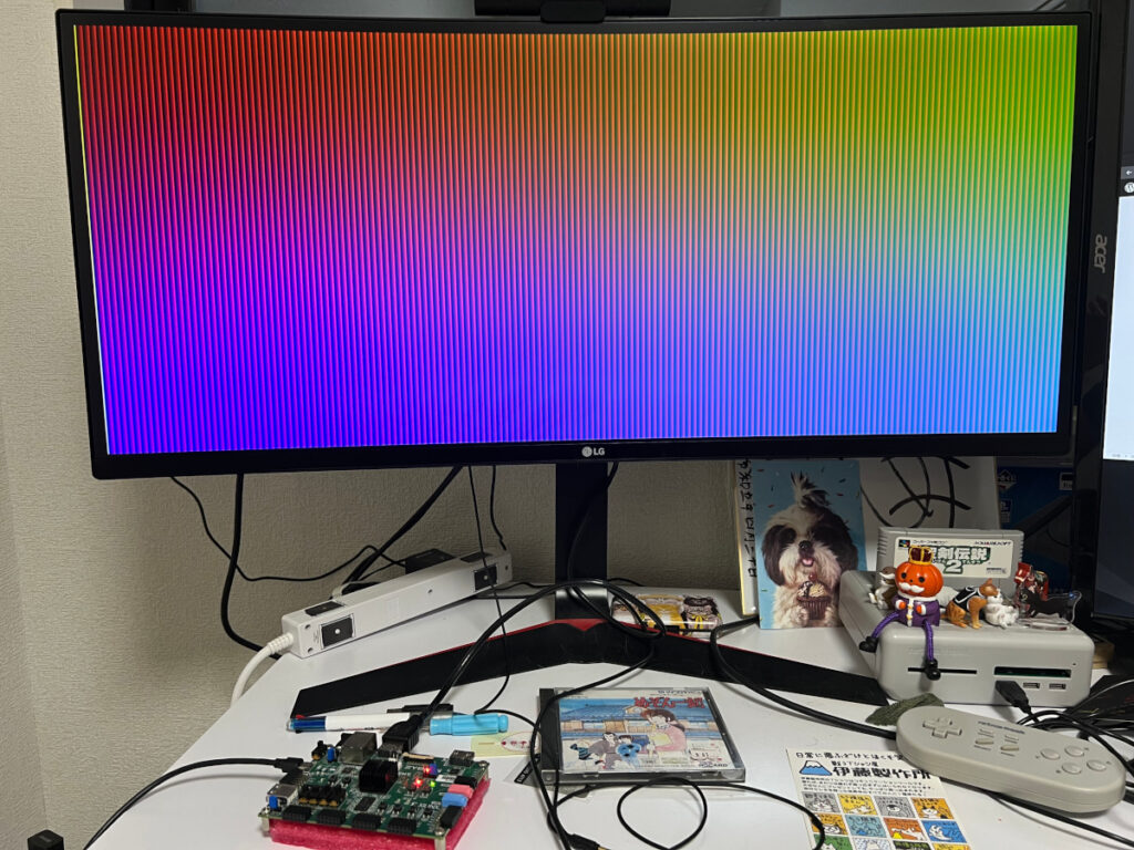
.TMDS_Data_n(hdmi_tx_n)); // output: 1b x 3ch negative HDMI dataAnd so now all that’s left to do is drive hsync, vsync, draw_area, and colour24. The easiest way to do this is to have a pixelX counter that goes from 0..799 and a pixelY counter that goes from 0..524. Hsync is asserted when pixelX is in the hsync area, vsync is asserted when pixelY is in the vsync area, and draw_area is asserted when both pixelX and pixelY are in the drawing area. It’s up to you what to do with colour24. You can output a solid colour, or use the pixel coordinates to generate a pattern. You have 10 + 9 = 19 bits of counter, so you can do something simple like this (but with localparam instead of magic numbers)
logic [9:0] pixelX = 0;
logic [9:0] pixelY = 0;

always_ff @(posedge pixel_clk_25) begin
	// update the counters
	pixelX <= pixelX + 1;
	if (pixelX == 799) begin
		pixelX <= 0;

		pixelY <= pixelY + 1;
		if (pixelY == 524) begin
			pixelY <= 0;
		end
	end

	// use the counters to generate a test pattern
	colour24[0] <= pixelX[9:2];
	colour24[1] <= pixelY[8:1];
	colour24[2] <= {pixelX[1:0], pixelY[0], 5'b0};
end

assign draw_area = (pixelX < 640) && (pixelY < 480);
// draw is [639:0], front porch is [655:640], sync is [751:656], back porch is [799:752]
assign hsync = (pixelX >= 656) && (pixelX <= 751);
// draw is [479:0], front porch is [489:480], sync is [491:490], back porch is [524:492]
assign vsync = (pixelY >= 490) && (pixelY <= 491);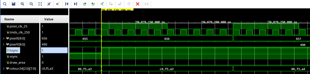
With the RTL done, it’s time to get something on screen. Ignoring simulation, the usual workflow is to run synthesis, implementation, and bitstream generation. Synthesis takes your RTL and produces a circuit representation called a netlist. Implementation takes that netlist and implements it for the FPGA you actually have. Bitstream generation produces the thing you actually program the FPGA with. So go to the flow navigator and run the above three steps in order. If it succeeds, it might be fun to open the implemented design and see all the reports and information available. You can see the schematic, see the board utilisation, find out about power, noise, and timing, among other things. It can all be a bit overwhelming at first, but you don’t need to worry about all that right now.
To program the FPGA and run, you must first connect. In the Flow Navigator, go to Open Hardware Manager → Open Target, and select Auto Connect. Finally click on Program Device, and in a few seconds, you should see your test pattern. Well either that or a solid black screen with no video signal. Exactly like graphics programming!
So that’s all for this time. Hopefully you are getting used to Vivado, and starting to get excited about making graphics hardware. Actually, at this point it might be worth it to just play around with HDMI for a week. You don’t need to make a full GPU to make a video game, as it can all just be done in HDMI without framebuffers. I encourage you to attempt some simple games to get started. Eventually I’ll discuss hooking up Famikon controllers (shift reg) and PlayStation controllers (SPI), but for now just use the buttons and switches on your board. Exact same process of uncommenting lines in the constraints file as we did for the clock and HDMI TX. Good luck!